 ;
;
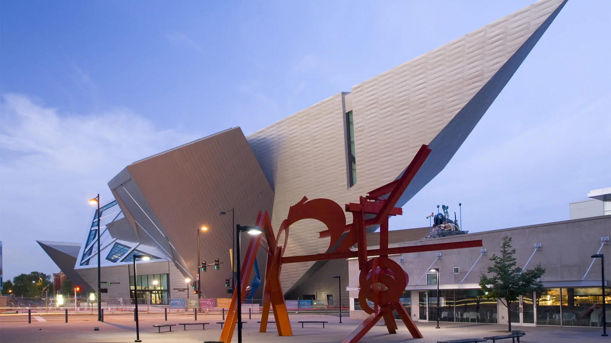
Inspired by the jagged profile of the nearby Rocky Mountains, the Frederic C. Hamilton wing of the Denver Art Museum has a silhouette more like a ship than a building. Indeed, Arup engineers looked at shipbuilding when they approached the engineering design of this extraordinary building.
Except for its central elevator core, the building has no true vertical walls. Its ceilings and risers slope at all angles. The engineering challenge was to create a stable supporting structure for a building that did away with typical means of support.
With walls leaning outward, the form required Arup to design the floor framing system to manage heavier lateral loads. Like a ship, the intended effect was to pull the exterior walls in to keep them from pushing out. Because the angled walls would deflect during construction, they were supported by a temporary shoring system that required extensive structural analysis so that the walls would settle into the correct position when the shorings were removed.
Denver is not an area prone to earthquakes, but because of the building’s challenging geometry, the structure was designed to withstand lateral forces beyond what would be required for regions with the greatest seismic activity.


To determine how to run the dedicated ductwork to appropriate areas within the irregular geometric form of the building, Arup employed three-dimensional modelling analysis and visualisation tools to create the structural, mechanical, and architectural forms. This modelling was subsequently shared with, and used by, other project partners, greatly streamlining and simplifying construction. The project marked the first time that 3D construction documents had been an explicit contractual requirement for Arup.
Using 3D, designers sought to resolve all geometrical problems during the design stage. With traditional 2D drawings, it is virtually impossible to anticipate potential construction conflicts between mechanical and structural elements. But with 3D, the size and shape of every duct and beam can be simulated, with potential conflicts pinpointed and resolved in advance. Where a duct intersects a steel member, for example, the penetration is first shown on shop drawings, which then can be used by the steel fabricator to make the required cuts precisely.
Museums have strict environmental quality requirements to protect artwork. In Denver, dedicated zone ductwork was run from centralised mechanical rooms to the galleries. By using 3D to model both structure and ductwork, the unusually angled ducts could be copied to generate pre-fabricated ductwork that could be installed with minimal reworking in the field.